Charles R. Goulding and Matthew Selman look at the shift from MCAD to ECAD tools for electronic circuit design.
Additive manufacturing of electronic components is an emerging application for electronic design and production. To successfully utilize this approach, software tools are required, however not all software is built alike.
A recent presentation from Mr. Joao Beck, the Director of Enterprise Tech Marketing at Altium in La Jolla, California, helped identify what an efficient design tool looks like regarding circuit design.
Electrical computer-aided design (ECAD) has the potential to overtake mechanical computer-aided design (MCAD) for 3D circuit design due to its prevailing capabilities. 3D designing of circuits in MCAD is a tedious process that can quickly become difficult with the spatial limitations and curvatures found on circuits.
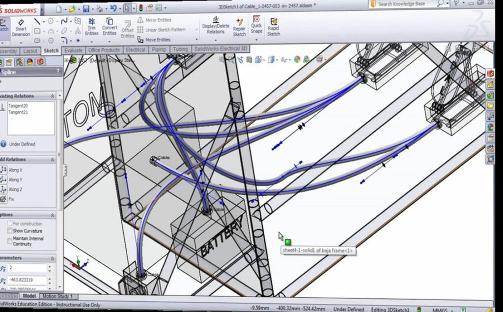
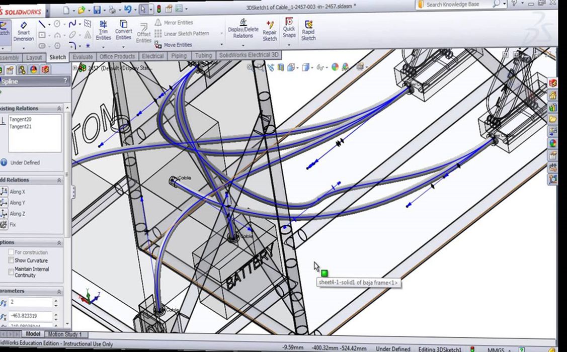
Common MCAD tools used to 3D model circuits, such as SolidWorks, lack the appropriate capabilities to allow for a perfect circuit design. Modeling within this MCAD tool leads to a disconnect and distortion of projected trace sketches because it is very difficult to model the component connections across a rounded edge.
Additionally, if there is a design with many components, the process of mapping all the connections becomes difficult and time-consuming because each connection has to be completed individually.
There is no component library so even commonly used components can not be easily imported into the model. The MCAD design requires visual checks for verification and the possibility of overlapping connections, which would otherwise result in short circuits or misconnections.
Circuit designs can be very complex. Some designs contain over 100 components, emphasizing how MCAD tools really lack the capabilities needed for an efficient board design.

ECAD tools seem to address all of the shortcomings of MCAD tools.
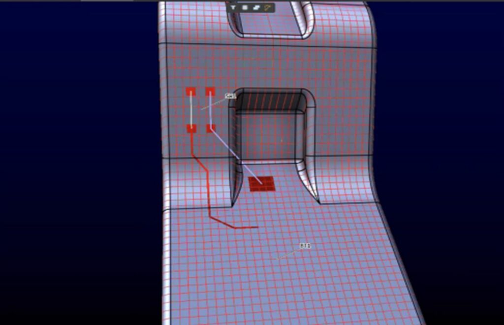
An example of an ECAD tool is demonstrated above, designed by Altium. With this tool, the user can easily trace connections. They can go around curves without distorting the trace, and the traces can be strategically mapped to allow for the most efficient spatial layout possible. This ECAD tool can effectively design angles and very small distance alignment or routing.
This is an important aspect because as circuit designs become more and more complex, they require smaller connections that still have to be placed efficiently to function.
Overlaps are not a concern as the tool provides logical connections that will not be touching—even for very small separations.
This ECAD tool also contains a component library with hundreds of thousands of components available. While this number is still large, it will continue to grow as more components are designed over time. This library allows parts that have been designed before, by the user or someone else, to be easily imported into the design tool.
The library can be filtered by characteristics of the component, such as manufacturer, type of component, etc. These parts can be used as imported or adjusted as necessary. Either way, it saves the user time by not having to start from scratch. The tool also allows the component to be easily rotated to change the view in the most logical way.
The Research & Development Tax Credit
The now permanent Research and Development (R&D) Tax Credit is available for companies developing new or improved products, processes and/or software.
3D printing can help boost a company’s R&D Tax Credits. Wages for technical employees creating, testing and revising 3D printed prototypes can be included as a percentage of eligible time spent for the R&D Tax Credit. Similarly, when used as a method of improving a process, time spent integrating 3D printing hardware and software counts as an eligible activity. Lastly, when used for modeling and preproduction, the costs of filaments consumed during the development process may also be recovered.
Whether it is used for creating and testing prototypes or for final production, 3D printing is a great indicator that R&D Credit eligible activities are taking place. Companies implementing this technology at any point should consider taking advantage of R&D Tax Credits.
Conclusion
ECAD tools are the superior option when it comes to 3D circuit design, as they are easier to use and enable the circuit to be more appropriately laid out. When working with an ECAD tool compared to an MCAD tool, engineers and designers can save both time and effort for circuit designs.
Efficient 3D circuit design is an important next step toward additively manufacturing electronics. 3D printing electronics is an industry that is looking to advance in the near future. The use of ECAD tools for improved circuit designs has the potential to make the 3D printing of electronics more of a reality.

