I found a very easy way to start non-planar 3D printing.
Hold on, you don’t know what non-planar 3D printing is all about? Let me tell how it works and why you’d want to do it.
First, you must know that virtually all 3D printing processes today are “planar”. This means that the object is built in perfectly flat layers, on on top of the next.
This is why your 3D print job preparation software is called a “slicer”. It’s because it takes a 3D model and literally cuts it into horizontal slices, which become the layers of the print. The 3D printer, be it FFF, SLA, SLS or DMLS, simply produces each layer using their respective fusion methods.
Why planar? It’s because of risk and simplicity. The problem is that the 3D printer cannot assume the geometry of an incoming print. Consider a scenario where you have two “towers” in the model. If the printer were to build one tower and then the other, it is possible that the printer might crash into tower 1 accidentally while building tower 2.
But if the model is built in planar form, the printer mechanism can simply stay “above the plane” and be guaranteed that it will never strike any portion of the previously printed layers. Take a look at an FFF 3D printer, for example: there’s absolutely NOTHING underneath the tip of the nozzle within the build volume.
This concept makes it very straightforward to develop slicing software that chops up models into easily built layers. It’s an approach that is proven to work.
But there are some challenges.
Extrusions in FFF 3D printing are essentially lines of polymer. These lines are quite strong if you were to pull on them because the molecules are literally bonded together throughout the length of the extrusion. However, when you stack lines on top of each other, as is done with printed layers, the bonding between layers is far less strong.
This means that FFF 3D prints are consistently weaker at the joints.
For decorative items, this doesn’t matter. But it really does for mechanical parts. Some slicers and 3D printer operators take considerable effort to orient their parts perfectly to ensure the layer lines are aligned with the expected forces.
If only you could print a 3D model in non-planar form to ensure the extrusion strength is exactly where you need it. However, that’s almost a fantasy because of the issue of being unable to avoid collisions as described above.
Nevertheless, there have been experiments with limited forms of non-planar 3D printing. We reported on one a few years ago, where bike helmets were being printed in non-planar form on “normal” 3D printers.
However, the problem is just so complex that it is basically impossible to create a general purpose non-planar “slicer”, if one could call it that. Non-planar 3D printing will forever remain a niche approach because of the mechanical and computational challenges.
That said, there are plenty of geometries that could indeed be printed in non-planar form because their shape would not generate collisions.
That’s where FullControl comes in.
FullControl is the product of Andy Gleadall of Loughborough University in the UK, who decided to create a GCODE generation software framework that could perform non-planar feats of 3D printing.
Gleadall explains:
“Upon becoming a lecturer, I realised that many students and researchers wanted to generate their own GCode but did not want to write scripts. They spent a lot of time learning programming and writing scripts, and had less time for doing the actual additive manufacturing work they were interested in.
That led me to see that a framework for GCode generation, based on simple human-understandable instructions, was needed.
I iteratively developed FullControl GCode Designer, and am now sharing it in the hope that people will find it as useful and empowering as my collaborators and I have. It’s allowed us to do things that would be impossible with scripts or slicers.”
You can head to the FullControl site and obtain the software framework to build your own experimental GCODE generator. It allows feats such as:
- Nonplanar print paths (e.g. zigzags in the highlight video on the home page)
- Neat continuous print paths (e.g. for difficult-to-print materials)
- Previously unimaginable structures (e.g. string scaffolds in the highlight video on the home page)
However, many people are definitely not software engineers and may find this challenging or impossible. To breach that barrier, Gleadall has also created FullControl.xyz, a site that can generate GCODE for various standard shapes on demand.

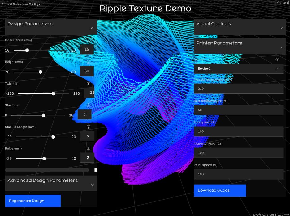
Using FullControl.xyz is easy, but it’s a very different workflow. Instead of creating a 3D model in a CAD program, you tweak a pre-made 3D model using parameters and directly generate the corresponding non-planar GCODE. This can then be 3D printed immediately.
The site also allows you to select from several popular 3D printer models to ensure the correct GCODES are prepared. As of this writing, the following seem to be supported:
- Prusa i3
- Ender-3
- Ultimaker 2 Plus
- E3D Tool Changer
- CR-10
Note that in reality these are actually “families” of 3D printer models. There are countless models of the Ender 3, for example. I suspect the GCODE would likely work on most desktop FFF 3D printers, but you may have to tweak some of the code.
Having an Ender-3 S1 handy, I thought I’d give this a try. I first selected a model and tweaked it a bit. The GCODE was generated and I set it up on the Ender-3 S1.
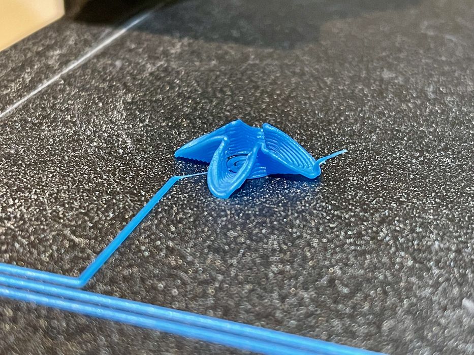
Watching the print was extremely unnerving. As the print proceeded, you could literally see the Z-axis rising and falling as the print deposited hills and valleys of the model.
Here’s another view showing the deposition in progress. I’ve never done a print like this, and it’s fascinating to watch.
The result was the crazy print shown at top. Take a close look and look at the layers: they are not flat! The extrusions were following the contour of the object’s design, as intended in this particular model. Incredible.

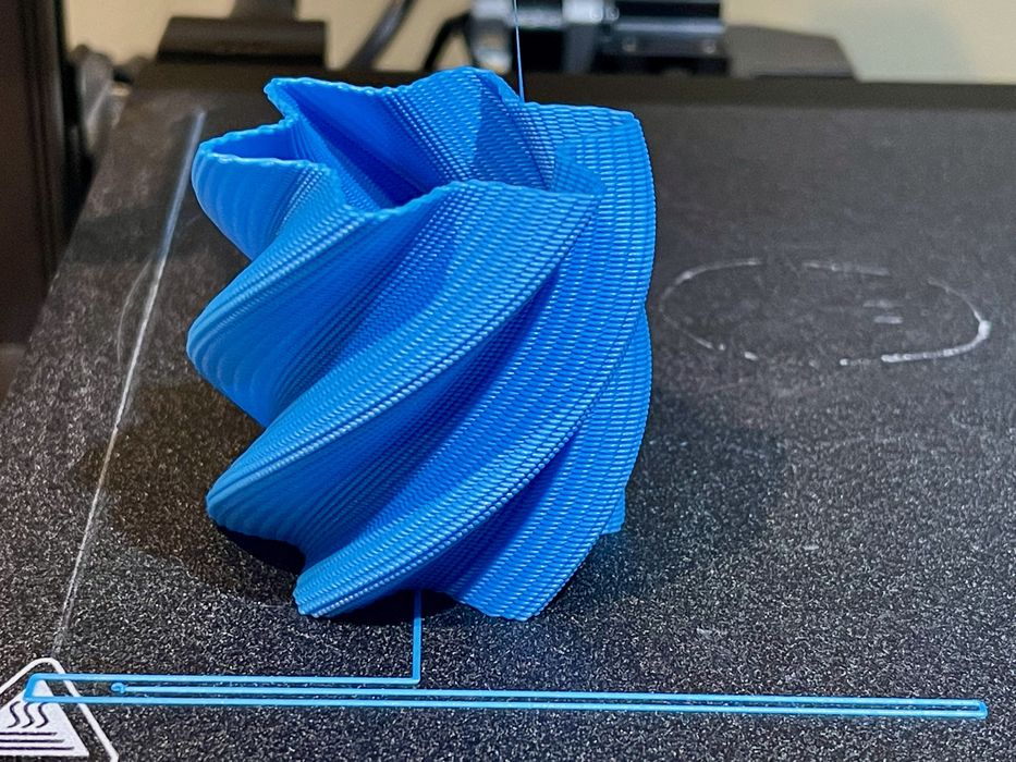
Here’s another example. But wait, you say, “that’s just a vase”.
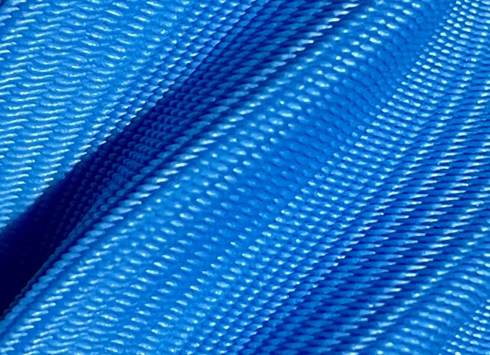
No, it isn’t. Look closer!

The extrusions are not horizontally sliced! They wobble up and down, making for an incredibly unique surface texture.
As of this writing, the FullControl.xyz site offers ten different non-planar base models that can be tweaked in various ways. Note that most of them are quite small in size, so you may want to pay attention to the sizing in the parameters.
It appears there are more models to come, and some even have a “countdown” until their official release.
The models presented are a combination of decorative and test models, such as the “2000-Retractions Test”.
If you’re curious about non-planar 3D printing, hit up FullControl.xyz and see it for yourself. If you’re into software, you may even want to acquire the open source software and build your own non-planar models.
Via FullControl.xyz and FullControl (Hat tip to Randy)

Well, just because you think only about plastics, doesn’t mean that technology exist. Almost all DED technologies (directe energy deposition), for metals, work this way.
And it’s a very promising thing that polymers (by means of FFF) works like this as well.