
How about no confusion and accuracy, for starters.
There are many methods for modeling in 3D. Here they are in order of increasing modeling sophistication and fidelity to the physical part.
- Points
- Lines, arcs, edges, also known as wireframes
- Faceted surfaces
- Smooth surfaces
- Solids
All 3D methods have advantages over 2D drawing, chiefly:
No confusion
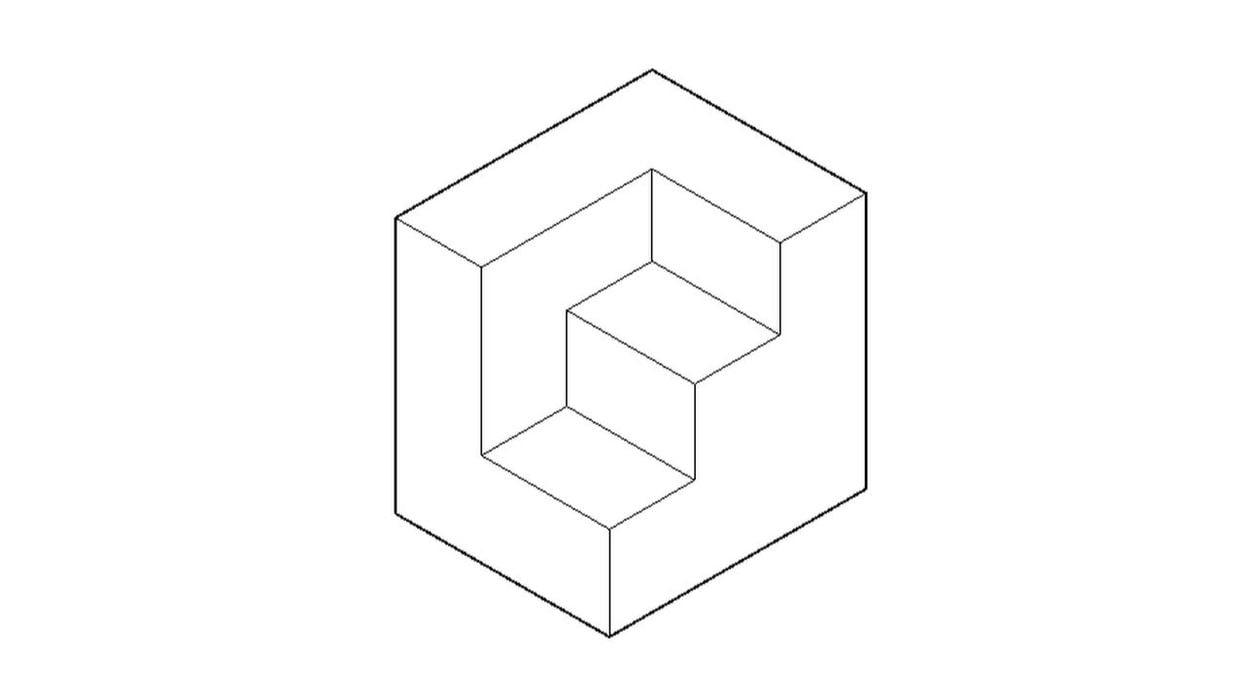
A part can be difficult to picture from its orthographic views. When this happens, the drafter in a 2D world is called upon to make an isometric view. Since this takes special skills, special tools and extra time, isometric views are rarely created, and their presence on a drawing is more the exception than the rule.
However, with the advent of 3D, surface and solid modeling in particular, it is common to show 3D objects with hidden lines removed and even shaded. You can spin a part around and look at it from any angle. You can zoom in and out. With surface and solid models, hidden lines are removed automatically (or shown dashed) and in real time. All this allows easy visual understanding of the shape of the part. There is no confusion.
Accuracy
3D models, as opposed to 2D drawings, are accurate by nature. 2D drawings rely on the creation of orthographic views. Each view is measured and created individually and independently of the other. Every line is made manually. At any point, you can make a mistake. Suppose, for example, a detail is moved in one view, but the other views in which the detail appears are unchanged. Or the detail is omitted in one or more views. Each part and all its details have to be considered in all the views and drawn accordingly. If it is hidden in a view, it should be shown with dashed lines. Each time it is drawn, it is a mental exercise and a source of potential error. An accurate and complete set of views is a tribute to a skilled and practiced drafter.
By contrast, a model made in 3D is made only once and then viewed from different sides. You don’t create the view, the software does. It’s like a physical object with a camera taking photos from different sides. Views are still often required on 2D drawings, but with a 3D model, view creation is done practically at the push of a button. And the isometric view, once a laborious exercise, is now a breeze.
Faster to the finish (almost always)
Creating a 2D drawing of a part may at first appear to be more expedient than making a 3D model. But it is a trap. Don’t fall for it. From the start, 2D requires extra time to do mental gymnastics to visualize the part, time to correct mistakes and time to make each view manually. After all this, a stack of drawings is dumped on tables in machine shops or construction trailers. Then the mental gymnastics are done in reverse — with the 2D drawings turning mentally into 3D, often after much head-scratching, time and too often mistakenly and inaccurately. But now, the mistakes are made in metal or concrete.
A 3D model, on the other hand, is a cinch to visualize. A machinist can spin it around and view it from all angles, as they would with the physical part in hand. The 3D model has the added benefit of being imported more naturally to CAM.