There’s an interesting new flow calibrator available that seems to work better than others.
Flow calibration has become far more important in recent years. With more advanced equipment able to print precision parts, the quality of the filament matters much more than it did before. That also goes for the flow rate, which determines how much material is being extruded.
If the flow rate is too high, you’ll see blobs and extra bits on the print, spoiling the surface quality. If it’s too low, you’ll see gaps that could not only mess up the finish but also weaken the part. Flow rate is very important.
Calibrating the proper flow rate for a given 3D printer – material pairing used to be quite manual and very few 3D printer operators bothered to do it. However, with the introduction of automated calibration features in SuperSlicer, things changed.
SuperSlicer introduced several calibration routines to dial in temperature, flow rate, retraction, and more. These features were so popular that they were adopted by other slicers, the most notable of which was OrcaSlicer.
I’ve used the OrcaSlicer calibration features many times, and it always helps to refine print quality, particularly when using new and unknown filament.
One of the routines is to calibrate the flow rate. To do so, the routine generates a set of small flat 3D models to print, each with a different flow rate. The idea is to visually examine each and figure out which one is closest to ideal. A second pass then dials in the exact flow rate with a finer resolution.
However, there’s a problem. It’s usually very difficult to discern any major difference between the printed flow rate samples because the extrusion pattern is a series of parallel lines. They just look the same in many cases, making it very challenging to nail the flow rate.
Enter the “Improved FLow Ratio Calibration V3” from MakerWorld contributor Jim Corner.
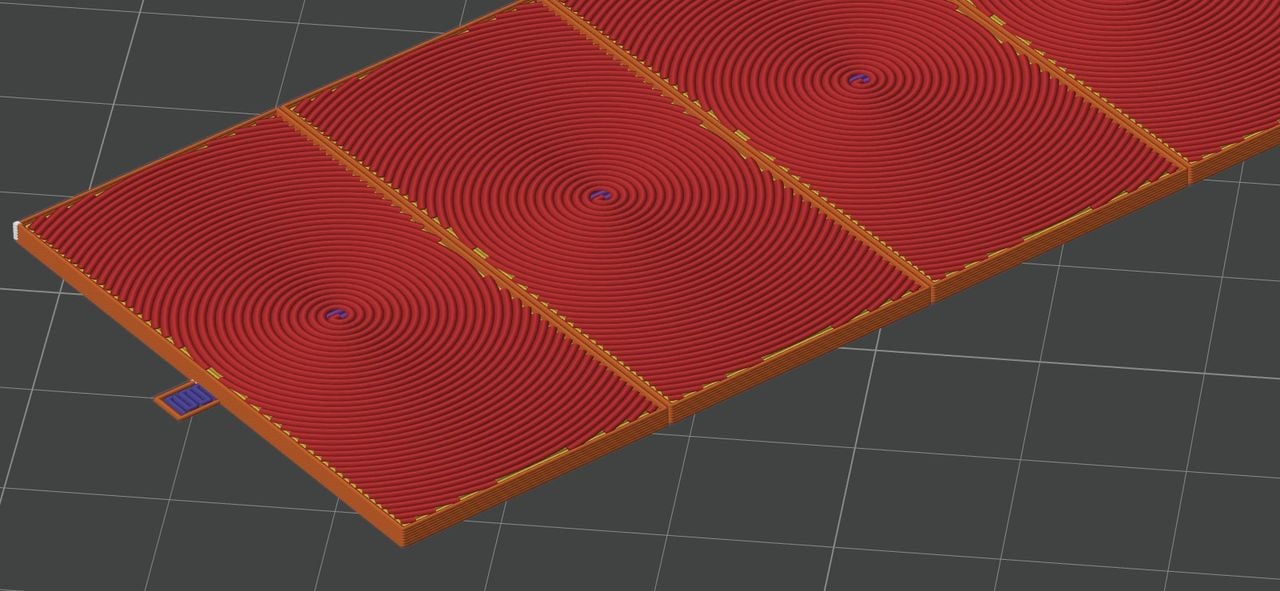
Corner has developed a similar two-step flow rate calibration process, but instead of using linear extrusions, they are circular. He explains why this is important:
“The top surface is Archimedean Chords pattern instead of monotonic, and line width is increased to 0.6mm, making it much easier to tell which flow rate is the best and take out the guess work.”
And:
“Here the Archimedean Chords pattern and larger line width of 0.6 amplify the effect of between-line-squishiness by inspecting the raised right half circle. As the flow rate goes up from the bottom to the top of the test pieces, the optimal flow rate would be somewhere when the raised right half circles start to appear as it means the lines start to get squished together.”

Above you can see a GCODE preview showing this circular pattern.
Another big change is that the samples are now physically connected, meaning you can’t drop the samples and get them mixed up.
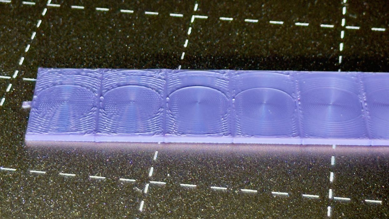
I printed the first step, as shown at top. As you can see, it is vastly easier to recognize the optimal setting. The circular patterns seem to overflow more easily and that’s clearly visible.
This calibration test does indeed work better than the stock calibration routines, so I will be using it in the future — and so should you.
My expectation is that this improved calibration routine will somehow find its way directly into the slicing software, making it even easier for everyone.
Via MakerWorld
