
We were provided with a resin pump for our new Form 4L 3D printer, and gave it a good test.
This is part one of a two-part series; please read part two.
Formlabs Resin Pump Background
Traditionally, Formlabs equipment has been served material through proprietary 1L cartridges. This allows the company to control the experience and automatically apply the proper print parameters to achieve the best possible print quality.
That works very well, but there’s one issue: capacity.
The company introduced the “L” series of machines starting with the Form 3L a few years ago, and now the new 4L. These devices have a substantially larger build volume, enabling them to print larger objects. The machines are equipped with two cartridge ports for extra materials.
Larger objects mean more resin is required, and for sometimes large items, more than two cartridges might be required, particularly if one was almost empty. Typically, the machine would pause and wait for the operator to swap cartridges and restart the job.
This problem is even more evident in a production environment where the machines are intended to run 24/7. One can envision operators busy all day and night swapping cartridges.
As we determined in our universal 3D print job cost calculator, by far the highest cost component of any 3D print job is always the labor cost. That labor, in this case, is mostly swapping cartridges.
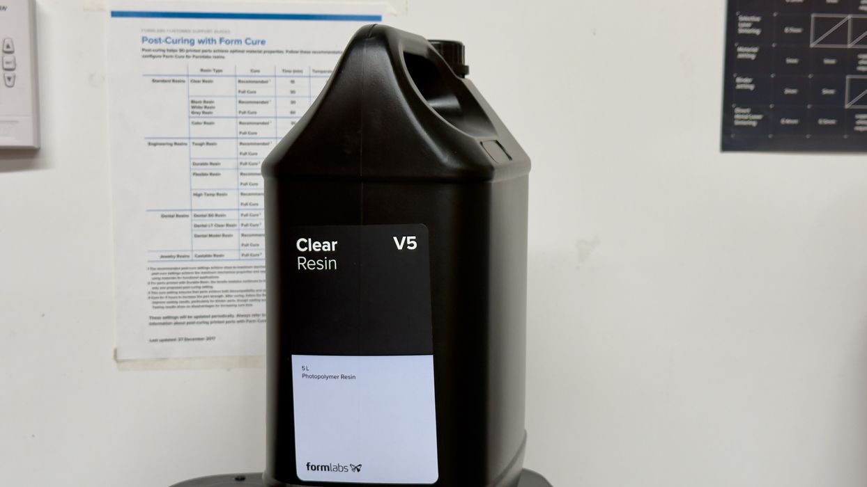
Formlabs recognized this and introduced two products that can overcome this problem: a 5L resin product and a resin pump system. Today, they market 5L jugs of Draft, Clear, Tough 2000, Model, and Grey resins.
The Form 4L is able to accept only the 1L standard cartridges, so how can you use a 5L jug of resin? Normally, the 1L cartridges are chipped to allow the 3D printer to instantly recognize the material type loaded into the machine.
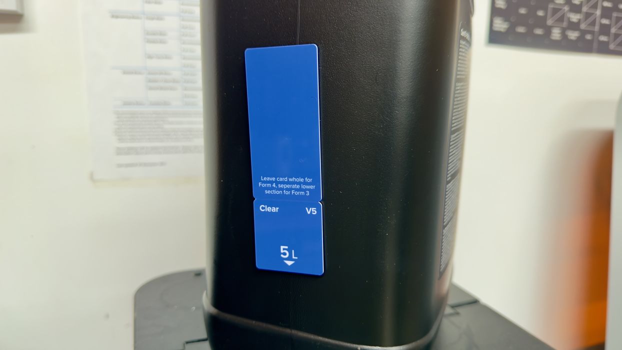
Formlabs overcomes this with an ingenious approach. Each 5L jug comes with a special chip card attached to its side. This is inserted into the pump system for it to understand the material type.
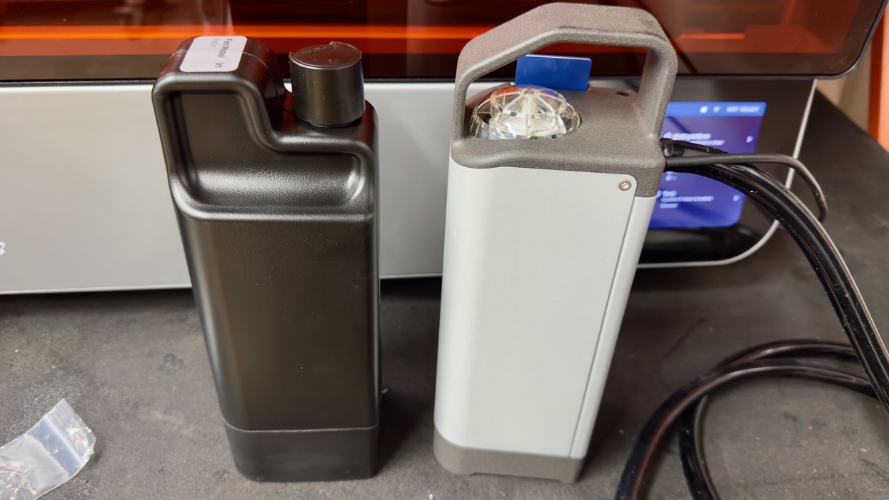
The pump unit itself is designed in exactly the same form factor as a standard cartridge. Above you can see the pump on the right, and a typical cartridge on the left.
There are two versions of the Resin Pump. One for the older Form 3 series, and another for the newer 4L series, which we tested.
Let’s put the Resin Pump system together and see how it works.
Formlabs Resin Pump Assembly and Setup
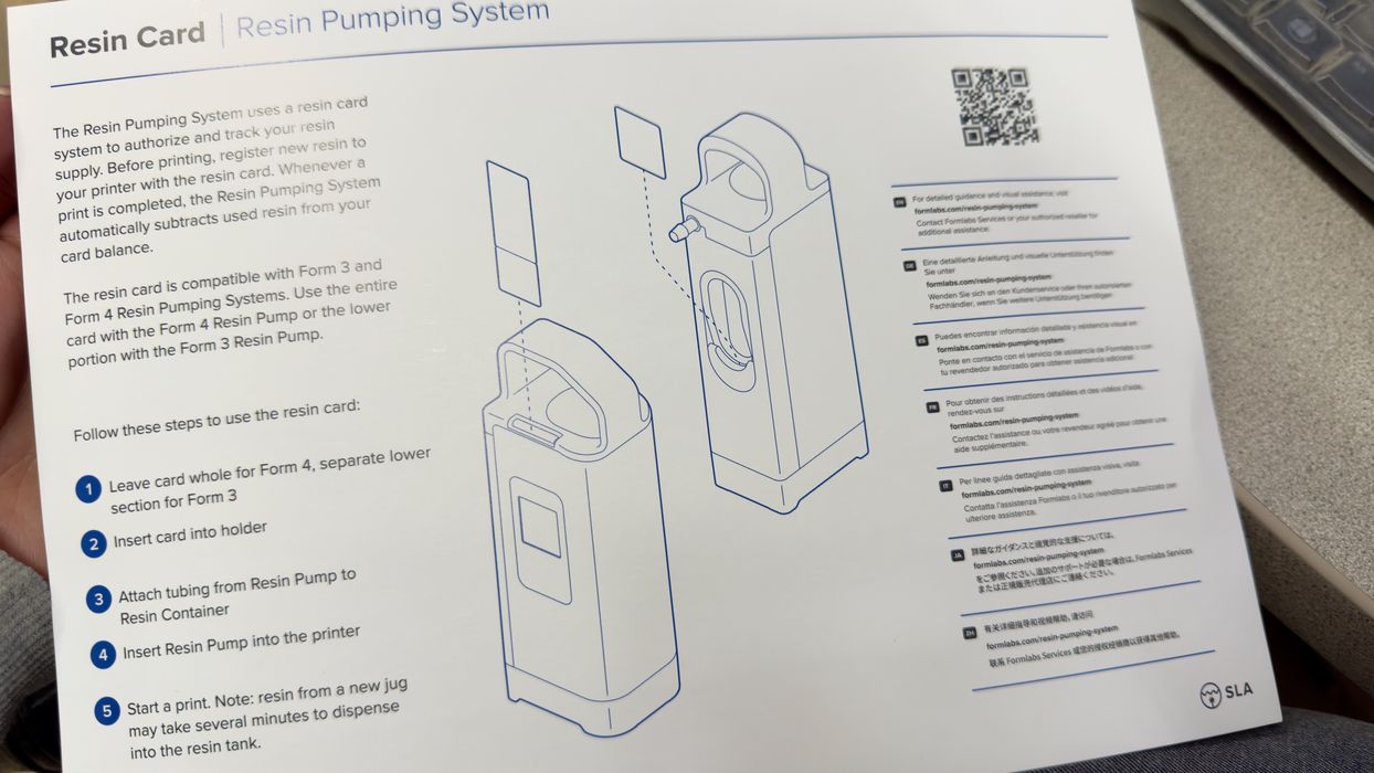
The pump system ships with a brief set of instructions, and there really isn’t that much to do. However, there are some considerations as you will see.
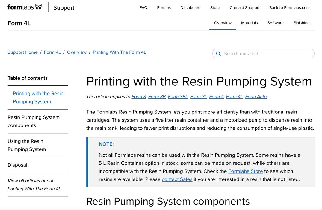
Formlabs also provides a webpage with more detail about the pump system and how to use it.
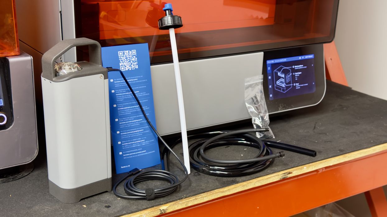
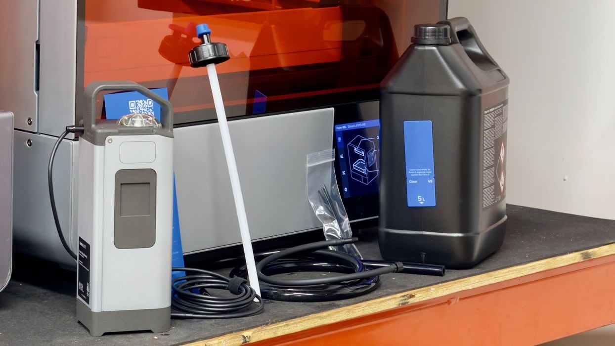
There are several parts to the system aside from the pump itself. There are a pair of tubes, a long USB control cable, a transfer cap mechanism, and tie wraps.
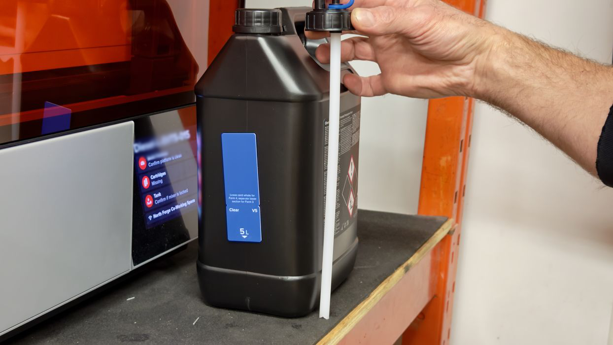
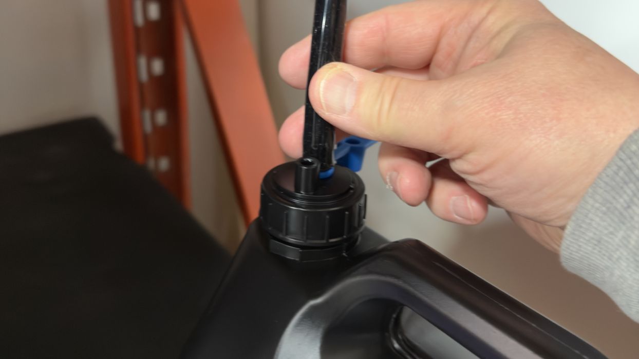
The transfer cap system is designed to replace the lid on the 5L jug. The length of the straw takes it right to the bottom of the jug, and it should be able to slurp up virtually all the resin in the jug.
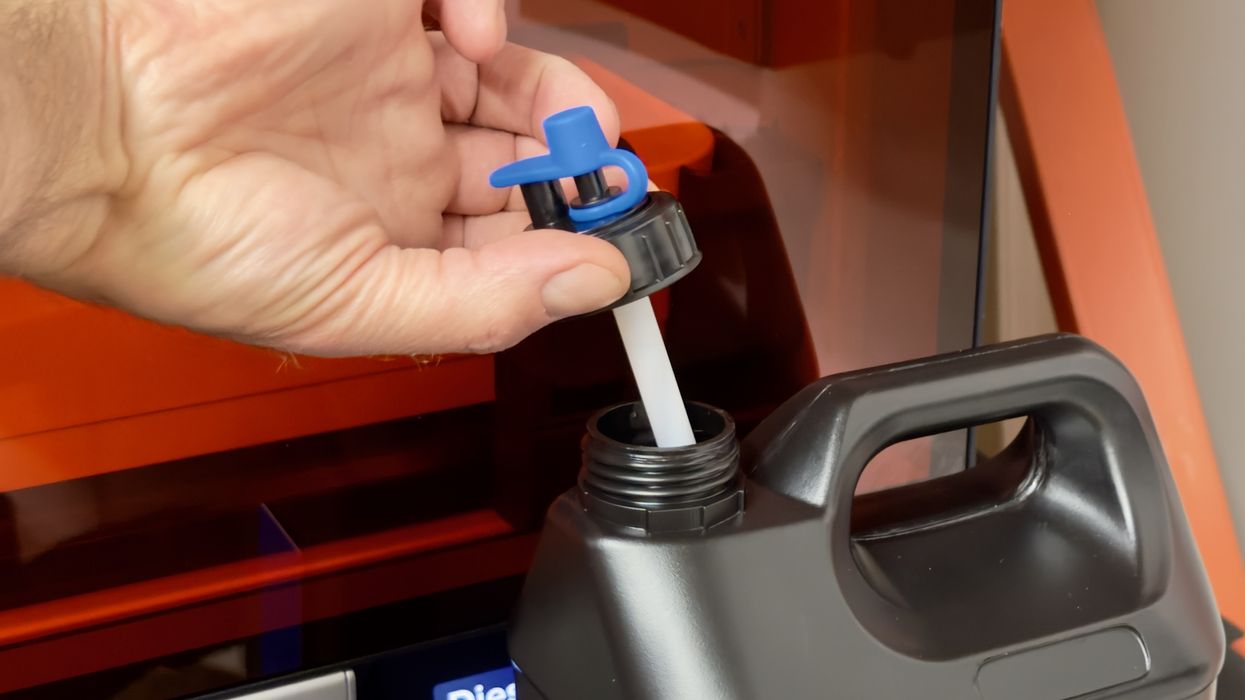
Inserting the transfer cap mechanism is straightforward; just take off the jug’s lid and insert it. However, at this point, we realized that the instructions had not told us to shake the resin jug.
Normally, this is good practice as resins tend to settle if not used. We thought it better to shake the jug while the original lid was on, in case some resin leaked through the transfer cap. Perhaps Formlabs should add that step to the instructions? Or maybe Formlabs resins do not require agitation?
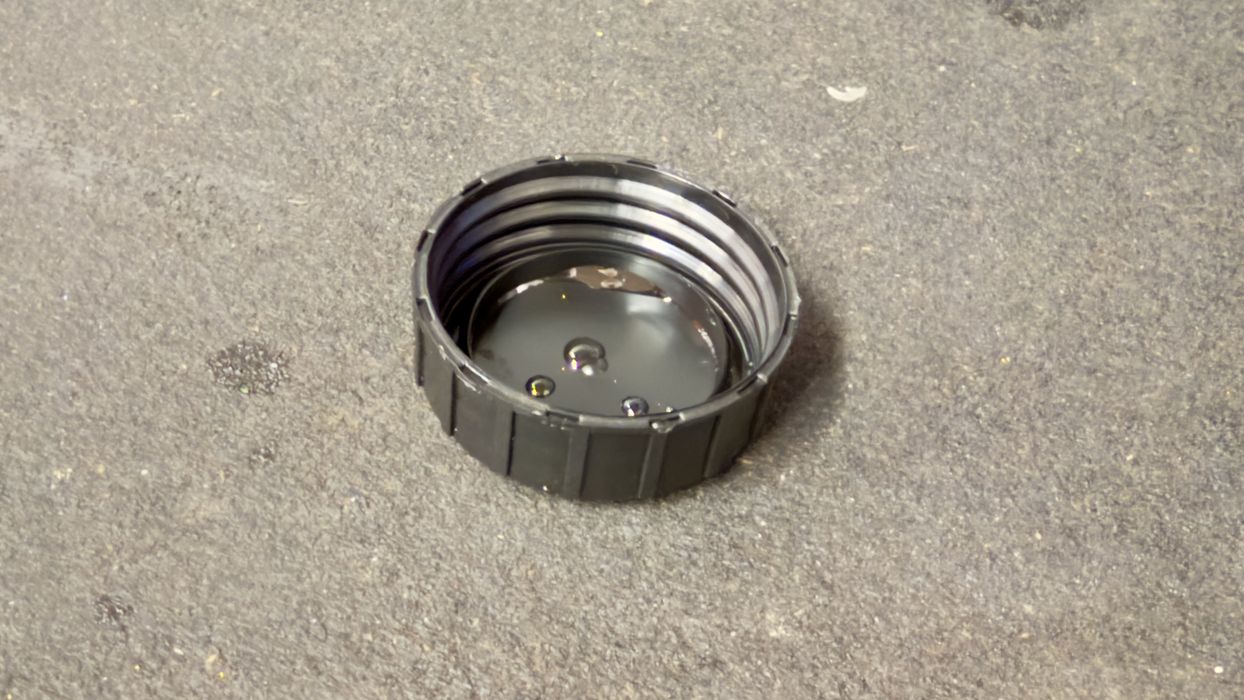
A problem we noticed with the pump is that after you insert the transfer cap, you’re left with the leftover lid. Eventually, it will be replaced on the jug when emptied, but what do we do with it in the meantime? There is no obvious place to put it, and it is covered with some resin due to the shaking. We suggest you have a spot where you can put wet lids nearby.
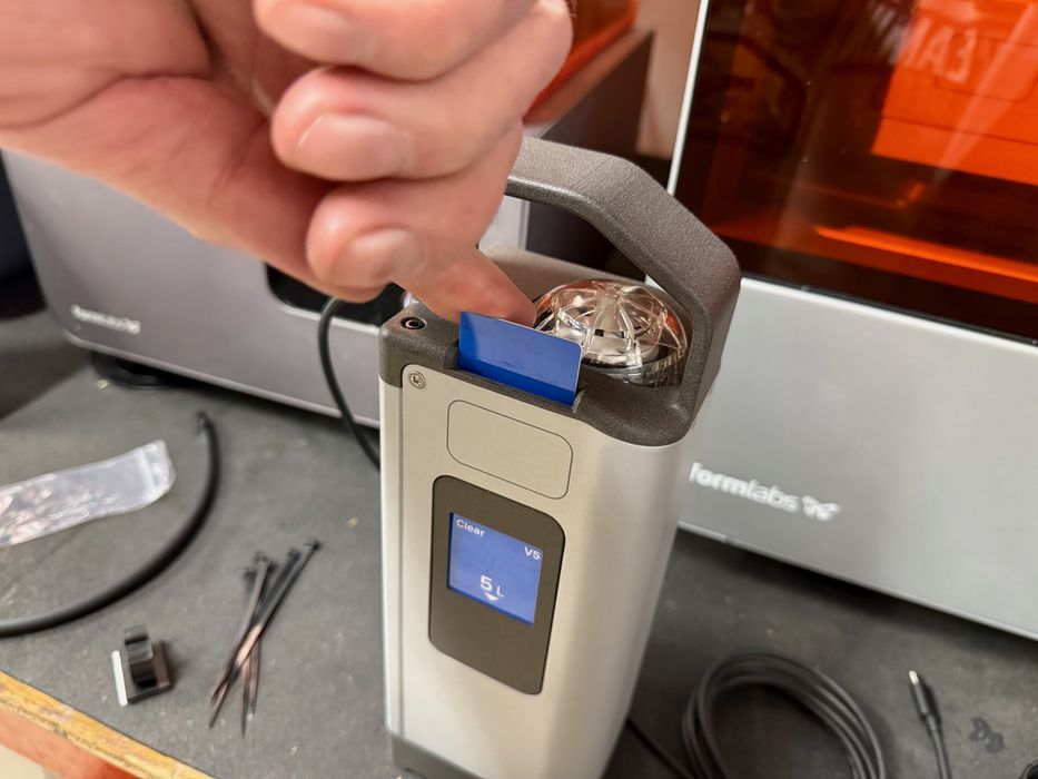
At this point, we pulled the chip card off the jug, which seems to be slightly glued. Note that these 5L jugs are usable by both the 3 and 4 series, but the pump design is slightly different. For the Form 3 systems, you must break off a short piece of the card for insertion, while the Form 4 systems can accept the entire card.
Here you can see how the pump looks with the card inserted. Note that the card is set up to present the chip in the exact same position as those on a standard cartridge.
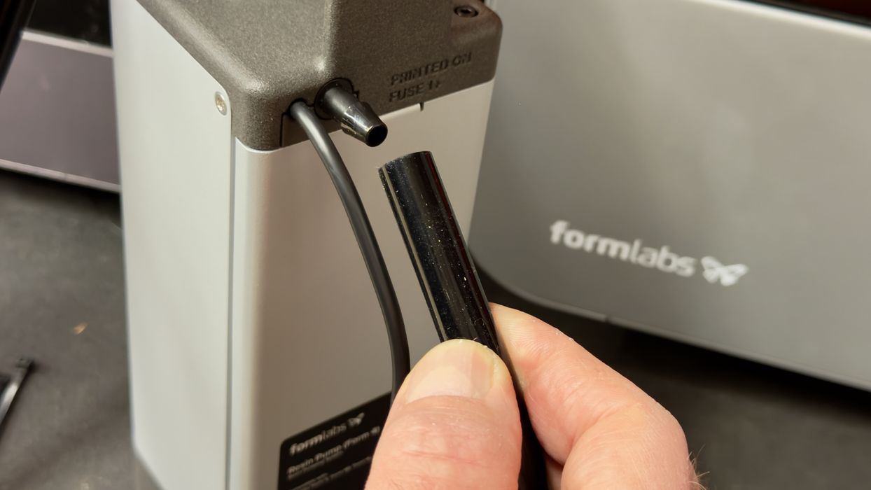
Now that the pump was ready, it was time to get the tubes hooked up. There are two tubes, with one being much larger than the other. This is the tube that carries resin from the jug to the Form 4.
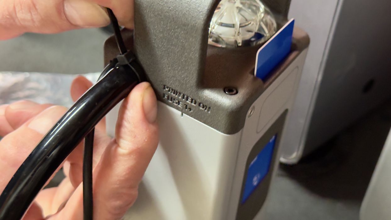
There are tie wraps to securely fasten the transfer tube to the jug; otherwise, there might be a mess.
What about that other tube? It turns out it’s a spare and would normally be used inside the pump.
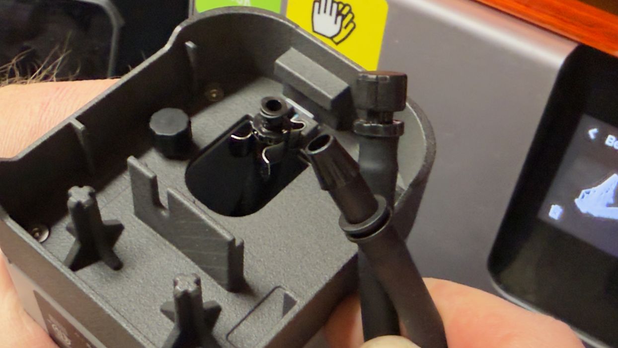
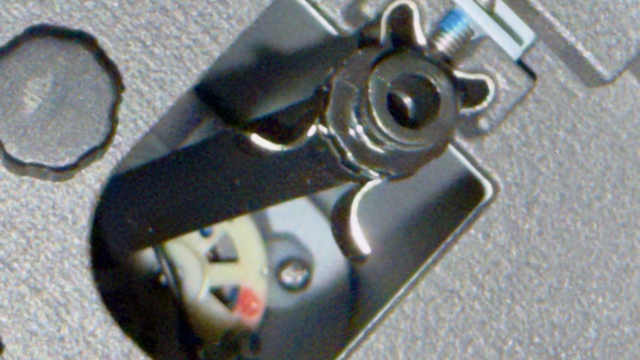
Here you can see how the end of this tube matches the geometry of the standard cartridge. It sits inside the pump and plays a key role in the action.
The pump is actually a peristaltic mechanism. Inside the pump, there are rollers that roll against the sides of the tube, pushing the resin forward. This isn’t like a normal pump, and there is a good reason for this that we will see later.
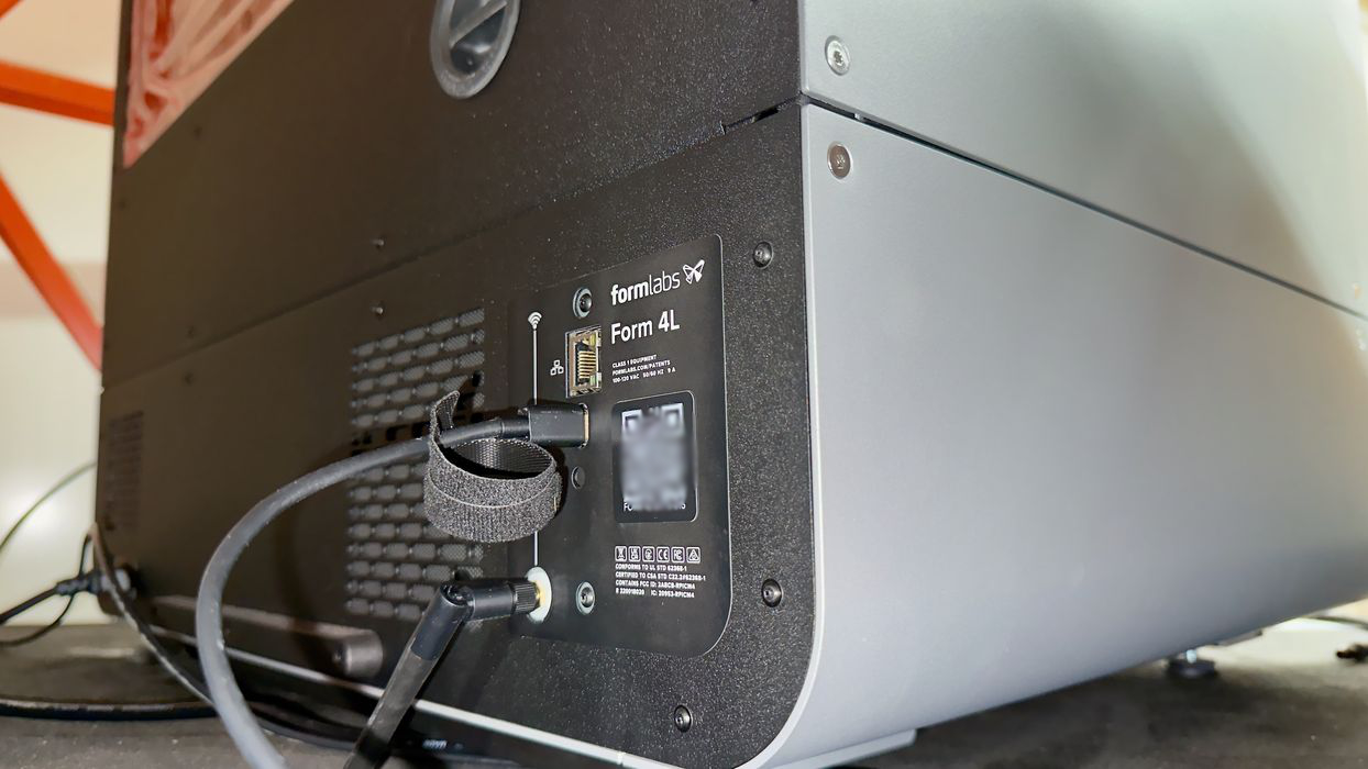
Another connection is the USB cable. This is how the Form 4 recognizes the presence of the pump and provides power for the peristaltic pump.
Unfortunately, the USB port is on the rear of the Form 4L, on the opposite side. This is quite a long run, but the cable is long enough to do so.
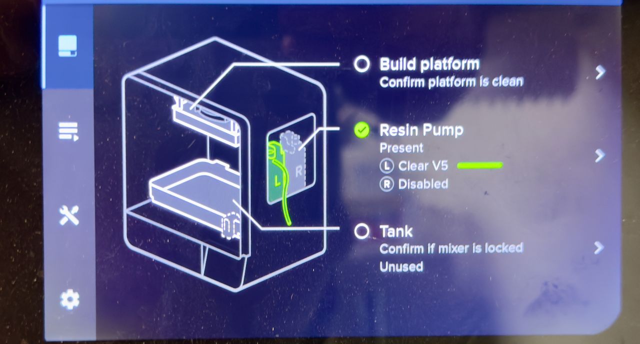
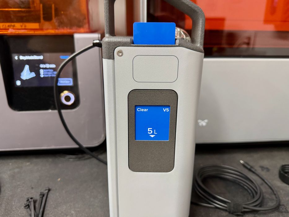
Immediately, the Form 4L noticed the pump, and the internal configuration was updated as above. Not only is the pump recognized, but the material type is also read from the inserted chip card.
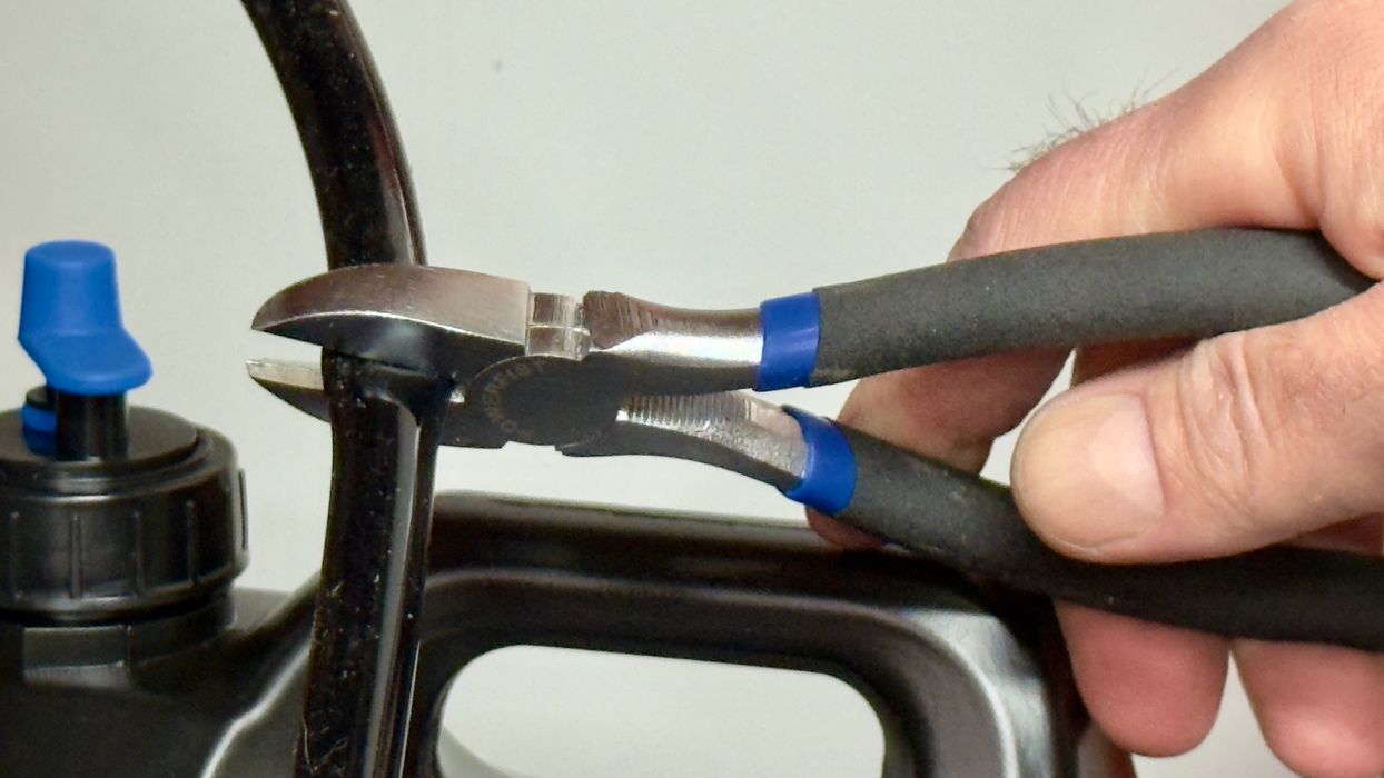
We noticed that the transfer tube was extraordinarily long and felt that pumping would take far longer due to this length.
We’re pretty sure that Formlabs included a tube of this length to allow for different customer situations where jugs might be placed on a semi-distant shelf, for example.
That wasn’t the case for our setup, as the jug was right beside the machine. We decided to chop the transfer tube to optimize the feed length. I believe that if you tightened up the distance between the jug and the machine, you might get three lengths from the original transfer tube.
Finally, we attached the shortened transfer tube to the top of the jug, and the system was ready to go.
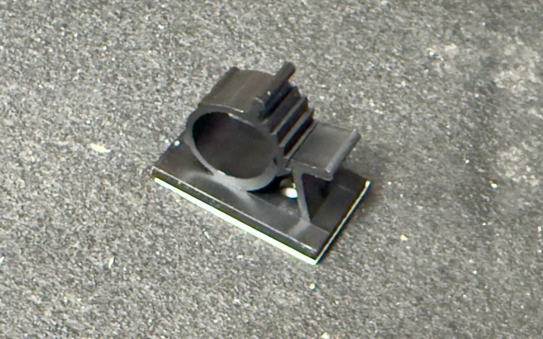
Hold on, there was this piece leftover. It’s a guide that fits the transfer tube. I imagine this could be useful if you had a long transfer tube and didn’t want it swinging around, but we didn’t need it.
With everything installed and recognized, we were ready to try it out.
This is part one of a two-part series; please read part two.
Via Formlabs