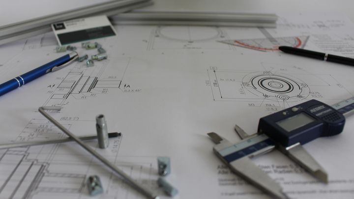
An engineering drawing is a specialized type of communication tool. It’s also a contract.
This particular communication protocol is designed to be complete, closed, and one way. This means follow up questions should not be required for the recipient’s comprehension and contractual agreement. It’s like a message in a bottle. With this, I present to you Dan’s 1st Law of Drawings:
Dan’s 1st Law of Drawings
The drawing shall communicate all information needed for fabrication as intended.
What is a Drawing?
A drawing is a two-dimensional medium used to convey the shape of a three-dimensional object. But where does the missing dimension go? A wormhole, a rift in the space-time continuum, the cracks in the sofa, the lint trap? It’s up to the imagination of the observer. We must use language and visual trickery to create the illusion of the missing dimension.
Shapes have a mathematical ideal, a perfect version that exists only conceptually and not in reality. This is despite my many many letters to governing bodies requesting they mandate real shapes that embody theoretical ideals. While the National Institute of Standards and Technology seems to be making small inroads, I’m not optimistic. Alas, for a drawing to be complete, it must not only describe the ideal but also the allowable variation from that ideal (cringe).
The amount of acceptable variation is called tolerance and impacts the design, function, appearance, cost, manufacturing processes, and lead time. Tolerance can be communicated in a variety of ways using a variety of standards. Tolerancing is a whole discussion topic(s) unto itself. But without tolerances, how nonideal an object can be is unspecified (not communicated) and open-ended. Anything open to interpretation may result in undesired interpretations and is ambiguous and therefore a violation of the first law. Violations of Dan’s codes are punishable by noogies and forced switching to decaf.
In addition to the shape definition, a drawing must contain all the other Product and Manufacturing Information (PMI). Examples of PMI include material, surface finish, coatings, weld information, process imparted artifacts, Bill of Materials, revision history and legal disclaimers.
What an Engineering Drawing Does
Engineering drawings describe a specific outcome. They don’t designate a process to get to the said outcome. One could create a process to create the desired outcome. Ultimately, a specific vendor will need to create an internal process to create the drawing’s resultant objective. Each fabrication process will be unique at some level. Drawings are intentionally process-independent to be general and not limit the vendor pool potential.
Getting the kind of cupcake one fancies could entail describing the cupcake or giving a recipe. When taking the recipe route, if the recipe calls for a special ingredient or utensil the baker doesn’t have then they won’t be able to make it. No cupcake. With a description, having some leeway provides for allowable variance in the ingredients and the process. This, in turn, should result in lots of hot fresh treats that are mostly similar but with minute differences. Some might even be better than your favorite recipe. Let’s not limit our cupcake intake.
Processes Can Be Tested
A nice thing about a process is that it can be tested. Simply follow the steps and check the outcome. Think of how code is routinely compiled to test it. For very complicated processes, one would break out process sections to check that they perform as expected in the context of the whole. Because drawings describe an outcome, not a process, testing must take on a different form. Testing is not as clean and linear as “compiling” and refining.
Read the rest at SolidSmack
