SPONSORED CONTENT
Injection molding is the process of injecting liquid thermoplastic into a mold.
Once the plastic cools, the mold is removed, and the object is ready for post-processing. When designing an object for injection molding, think about how the plastic will flow and how the mold will be removed after the part has cooled.
Uniform Wall Thickness To Avoid Warping
Warping is one of the most common defects of injection molding. As thermoplastic cools, it shrinks; if one part of the object cools faster, it will shrink more quickly, resulting in permanent deformation.
Warping can usually be avoided by using a uniform wall thickness across the entire design. Ribs and other structures can be used in areas that need additional support, but make sure that the ribs are the same thickness as the walls.
For easy cooling, always use the thinnest possible thickness for your design. This will help prevent sink marks, which are caused by uneven internal cooling. 1-millimeter and 3-millimeter thickness are recommended.
Corners often cool faster than walls, so remember to round all edges in your design. Use an internal fillet with as wide of a radius as possible so that the thermoplastic can flow smoothly through the mold.
Smooth Geometry Changes To Avoid Knit Lines
Knit lines occur when two separate flows of thermoplastic meet within the mold. These lines often ruin the aesthetic appeal of the design, and they also reduce the internal strength of the object.
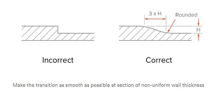
You can avoid knit lines and other problems by creating designs with smooth geometries. Avoid areas where the plastic must suddenly flow upward or downward. Use gradients instead of sharp transitions and curves instead of sharp turns. If an abrupt geometry change is simply required for the function of the object, consider designing an individual part that can be attached after manufacturing.
Draft Angles To Avoid Drag Marks
Drag marks occur as the object is removed from the injection mold. They can be avoided by designing draft angles that allow for easy removal.
Draft angles should be added to all vertical walls unless the angle of that wall serves a functional purpose. An angle of at least 2 degrees is recommended. For parts taller than 50 millimeters, increase the angle by 1 degree for every 25 millimeters of length.

How To Deal With Undercuts
A standard two-part injection mold cannot create an undercut; when the thermoplastic cools, the material will prevent the mold from opening. Depending on the shape of the object, designers use a variety of methods to get around this problem.
External undercuts can be created if the parting line of the mold is moved to intersect with that area. This technique may require an adjustment of the draft angles.
If the material above or below the undercut isn’t necessary for the part’s functionality, it can be removed from the design. Use a shut off to prevent plastic from flowing into the undercut.
If the chosen material is flexible enough, the mold can be deformed during the ejection process. This technique is often used to create threaded holes and other minor design features. Warping the mold to remove the object will increase labor costs for the project.
In some cases, the only way to create an undercut is with the use of a side-action core. Side-action cores are removed before the mold is opened. This increases the price of the original mold but allows for a smooth manufacturing process.


Adding Common Design Features
-
Ribs are used to improve stiffness without increasing the wall thickness. Ribs should be half of the main wall thickness and should be shorter than 3 times their own thickness. Remember to use draft angles for easy removal.
-
Bosses are used to attaching screws to the design. Bosses shouldn’t merge with the main wall; instead, they should be attached to the wall and supported by ribs.
-
Living hinges are created from flexible thermoplastic materials. The hinge will be thinner than the main walls, so create shoulders that are of the standard thickness.
-
Snap-fit joints are frequently used to attach two thermoplastic parts. Draft angles are essential to avoid warping the joint. Designers should consider how to deal with the resulting undercut.
-
Crush rubs are an inexpensive way to attach bearings or inserts to a design. When designing crush ribs, remember to add an overlap between the rib and the insert. The hole will require draft angles, but the ribs should not be drafted.
-
For threaded areas, add a relief of at least 0.8 millimeters at the edge of the thread, and make a plan for the resulting undercut. Threaded inserts can be used to make the design less complicated.
-
Embossed text is much easier to create than engraved text. The text should be aligned perpendicular to the parting line, and the font size should be at least 20 points. Avoid fonts with serifs or complicated features.
Learn how to select the right manufacturing process for your parts. 3D printing for low-cost & fast prototyping. Sheet metal fabrication services are more cost-effective than CNC machining when it comes to metal components with uniform wall thickness.
