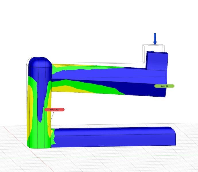
![A part undergoing static stress simulation in Autodesk Fusion 360 [Source: Fabbaloo]](https://fabbaloo.com/wp-content/uploads/2020/05/image-asset_img_5eb0a4e6c74e0.jpg)
Simulation is an amazing technology for designing parts, but it’s harder to do when 3D printing parts.
What is simulation? It’s an offshoot of 3D CAD design in which the part design is subjected to a variety of analyses. Using the results of each analysis, the design of the part can be adjusted to resolve any issues identified by the simulation.
A simulation involves the identification of various forms of stress on a part design. These are most typically mechanical stresses, which analyze how forces affect all portions of the design. Other types of analyses could include thermal, vibration, buckling, or more.
It enables a kind of virtual testing sequence, in which a design is “simulated” using an approximation of real-life conditions. The design is re-formed to account for issues and then re-simulated. This continues until the design is able to handle the simulated conditions.
It’s a short cut to the traditional approach, which would be to physically produce the part and then perform actual physical testing on it. Since part manufacture is expensive and time consuming, the virtual simulation is an incredible time and cost saver.
Simulation features are included in more advanced 3D CAD tools, such as SOLIDWORKS and Fusion 360, but there are many different add-on products that can perform simulations of various sorts. Some provide “rough” testing that’s quick to execute, but with less accurate results. Others provide more accurate simulations but at the cost of compute time. There are even some that act in real time, but they tend to require considerable desktop computing power or close links to a cloud system with same.
At this point you must be thinking that simulation would be incredibly useful to 3D printing, as parts could be tested before printing.
Well, that turns out to be not necessarily the case.
The problem is that many 3D printing processes are not isotropic, meaning the part produced does not have the same strength in all directions, as one would expect to find with a uniform distributed material.
Let’s contrast two identical parts, one made by injection molding, and another made by 3D printing.
The injection molded part has continuous material extending in all directions, and the molecules within the part are bonded more or less equally regardless of orientation.
The 3D printed part if made using a plastic extrusion process will typically be made by laying down lines of extrusion. These lines individually are as isotropic as the entire injection molded part, but a collection of them is not: the bonding between layers is far less strong simply because there is less material present. In many cases there are actually gaps between layers if you were to look microscopically.
The simulation systems typically assume that the material is uniformly distributed and perform their calculations as such. For an injection molded part the simulation results could be close to correct, while the 3D printed part’s simulation would not be so.
3D printing introduces vast amounts of complexity to simulation. Another factor is the fact that many 3D prints are not solid: the interior of a part is a sparse matrix of infill.
There are a few 3D printing processes that do indeed produce isotropic parts, but you still have the infill issue. Even with metal 3D printing, variations in the laser power may cause meltpool crystallization to be somewhat different than the stock material properties in the simulation tool.
The bottom line here is that off-the-shelf 3D CAD simulation systems may not be correct for 3D printing, and that highly specialized tools may be required for proper simulation analyses.


