Rotational bearings are something many folks attempt to 3D print, but end up disappointed.
Standard bearings are often not very usable due to the relatively inaccurate production by common desktop 3D printers, as the movable components are often small in comparison to the resolution of the 3D printer. However, there is a way you might be more successful.
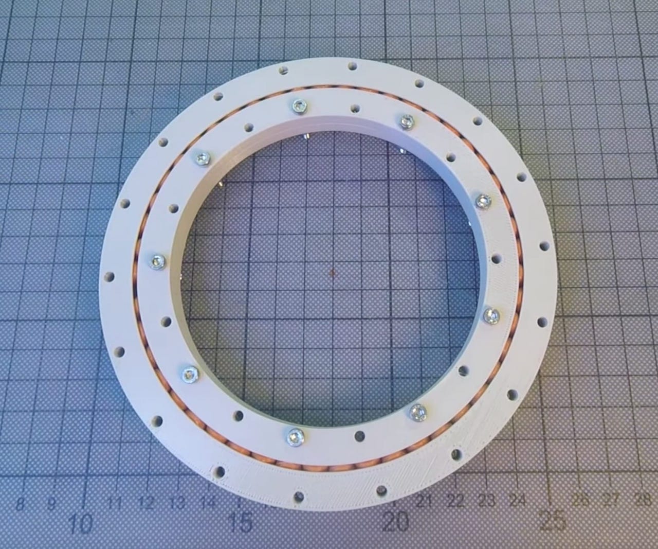
Creator Christoph Laimer has produced a design for a slew bearing that could be better produced on 3D printers.
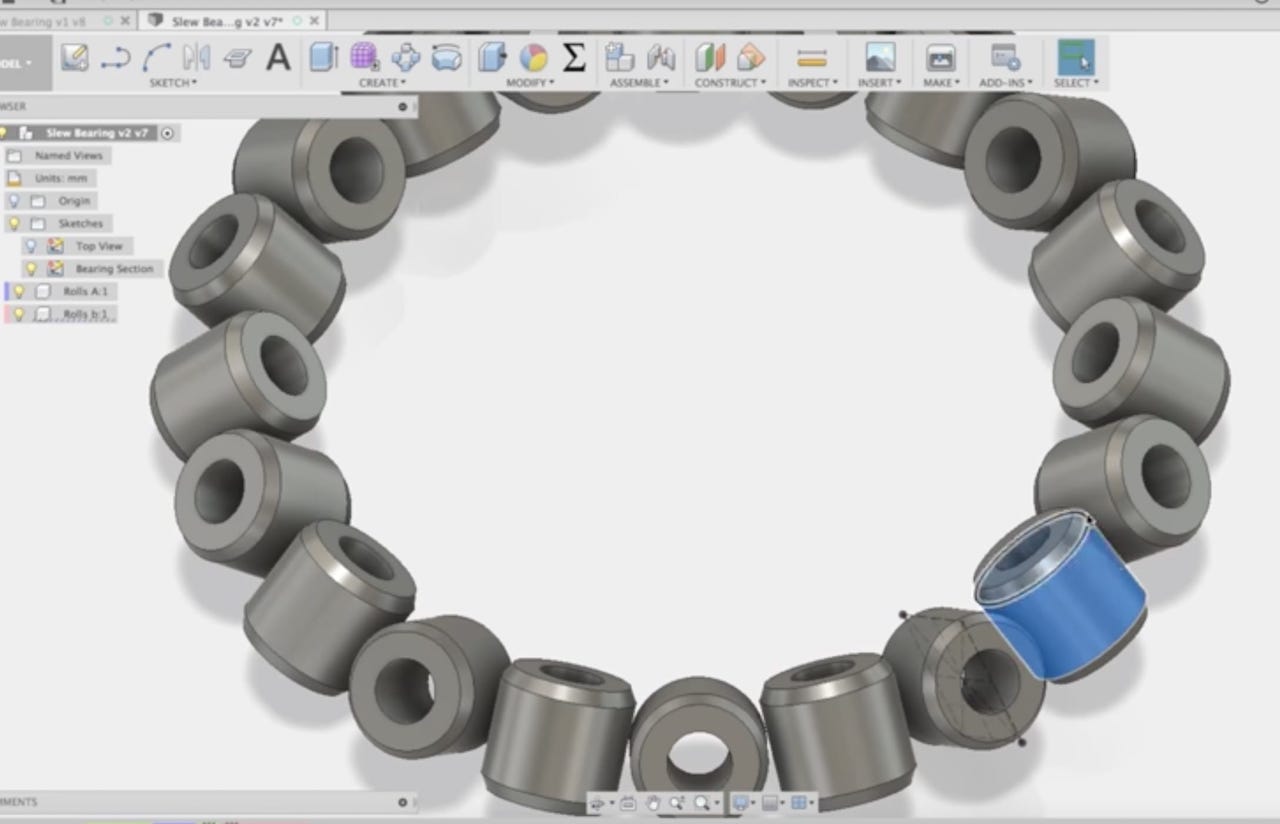
But what is a slew bearing? It’s a different kind of bearing design. Where a common bearing has a number of balls or rollers configured identically in a ring, the slew bearing is shifted 45 degrees to the side.
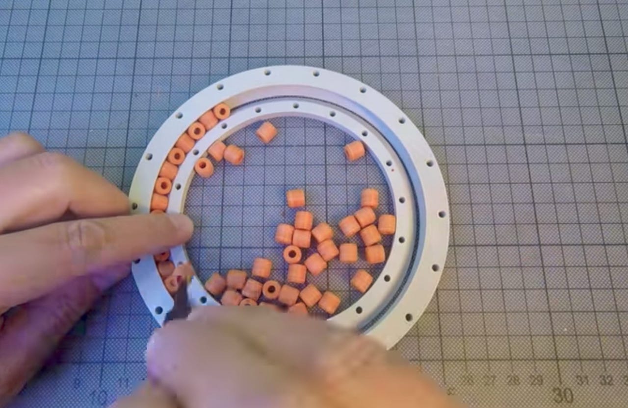
The bearings are not balls, but cylindrical rollers that are installed in alternating directions in the ring as shown here.
According to Wikipedia:
A slewing bearing or slew[ing] ring is a rotational rolling-element bearing or plain bearing that typically supports a heavy but slow-turning or slow-oscillating load, often a horizontal platform such as a conventional crane, a swing yarder, or the wind-facing platform of a horizontal-axis windmill. (To “slew” means to turn without change of place.)
Slew bearings are typically used for larger rotating elements, which is why this approach may be more successful with 3D printing.

But how do you design such a complex structure? It turns out that Laimer has not only produced a slew bearing 3D model for download, but he has also produced a 25 minute video that takes you through the process of designing a custom slew bearing 3D model.
While you could attempt to do this design yourself from scratch, I highly recommend watching Laimer’s detailed video, where he explains critical details, such as establishing the correct gaps between components, or the mathematics required to determine element sizes.

Once designed, the bearing should be easily 3D printable on reasonably sized desktop 3D printers with a resolution that will make this bearing design work properly.
Via Thingiverse and YouTube

