Developers of Siemens NX are working to integrate mesh data for everyday CAD users.
Siemens, for both NX and Solid Edge, calls its marriage of meshes—referred to as facet, or polygonal models—and NURBS-based models—known as B-rep models—convergent modeling. Siemens takes “convergent” to mean multiple types of models are coming together in a single application interface. “Hybrid” is the other term applied to mesh and NURBS geometry in the same model, although hybrid has also been applied to many combinations, such as wireframe and surfaces, surfaces and solids, direct and history-based, and now mesh and NURBS data.
The future that vendors hope to address with hybrid modeling is already here. The addition of non-NURBS data to a NURBS-only CAD world is more and more common. Tools to work with mesh data are being increasingly incorporated into engineering software, from the high-end PLM suites to the mid-range and lower levels of CAD.
What kinds of items do we find in a mesh format that we might want to use in a NURBS/B-rep CAD modeler?
- Mesh models use analytical surfaces for mating
- FEA uses mesh for analysis
- 3D scans yield mesh (point cloud) results
- Medical MRI and CT scans
- Textures can be applied via mesh
- Generative design produces mesh data
- 3D prints can be made from mesh data
- Display data uses shaders working with tessellated point clouds
- NX CAM can machine from double accuracy mesh data
- AEC applications need scanned data of terrain for civil engineering and architectural planning
Convergent modeling was first announced by Siemens in 2016. It is meant to make working with different data types seamless and transparent to the CAD user.
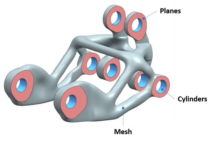
A great example of this is shown in the part below. The part was created by generative design, one of the technologies that convergent modeling was meant to originally support. But the mesh model generated by the generative process was just a stand-alone part. You couldn’t use it anywhere because none of the holes were really holes, and none of the planes were perfectly flat. You couldn’t mate this into an assembly. The model needed to contain two different kinds of data: point-based data for shape and analytical surfaces for function and mating.

To add analytical geometry to a mesh model is probably one of the most basic requirements of convergent modeling. Very few products are actually stand-alone parts. Almost everything that is manufactured is put together with something else in a fashion that requires functional surfaces, such as planes and cylinders. These analytical surfaces might represent secondary processes, including machining, grinding, drilling, broaching, reaming or tapping.
So, we have to move on to assembling parts built using non-traditional means with traditional parts. At this stage, we can use mesh in the form of finite element analysis.
Read more at ENGINEERING.com
